When designing components for demanding applications, the effects of thermal expansion and contraction are challenges that can’t be overlooked. If materials are repeatedly exposed to extreme thermal cycles, they undergo changes that impact both their structural integrity and performance. In this article, we explore how engineers can better understand and mitigate the risks of thermal fatigue and thermal shock - two key factors that affect material durability and reliability over time. Read on to learn more about what calculations to use to select materials with high thermal fatigue and shock resistance parameters to keep your designs performing at their best under tough conditions.
Due to thermal expansion, objects will expand when heated and contract when cooled. If such an object were completely unconstrained, the change in dimensions can be computed from the thermal expansion coefficient. However, solid objects in systems are rarely completely free to expand and contract without limit. When the material is prevented from expanding or contracting by the required amount, then the material experiences thermal strain and thermal stress.
Heat checking, or thermal fatigue, can happen when a surface is heated and cooled repeatedly, which commonly occurs in molds used for die casting, or with injection molding of liquid metal. When the metal surface comes into contact with liquid that is several hundred degrees hotter, the surface will quickly heat up and expand. Meanwhile, the core of the metal is still at the initial temperature. If the material has poor diffusivity, there will be a large gradient in temperature between the surface and the core, and thus a large gradient in thermal strain and stress as well.
The surface will want to expand greatly, but it will be constrained by the core material below, which effectively puts compressive stress on the surface. At a high enough temperature, the stress will exceed the strength of the material, and it will stay in that state. When the thermal load is removed and the metal is allowed to cool, the surface will be unable to shrink as much as the core, since it has been permanently deformed. This places the surface into a state of tensile stress. Over many such cycles of alternating compressive and tensile stress, fatigue cracks can develop on the surface.
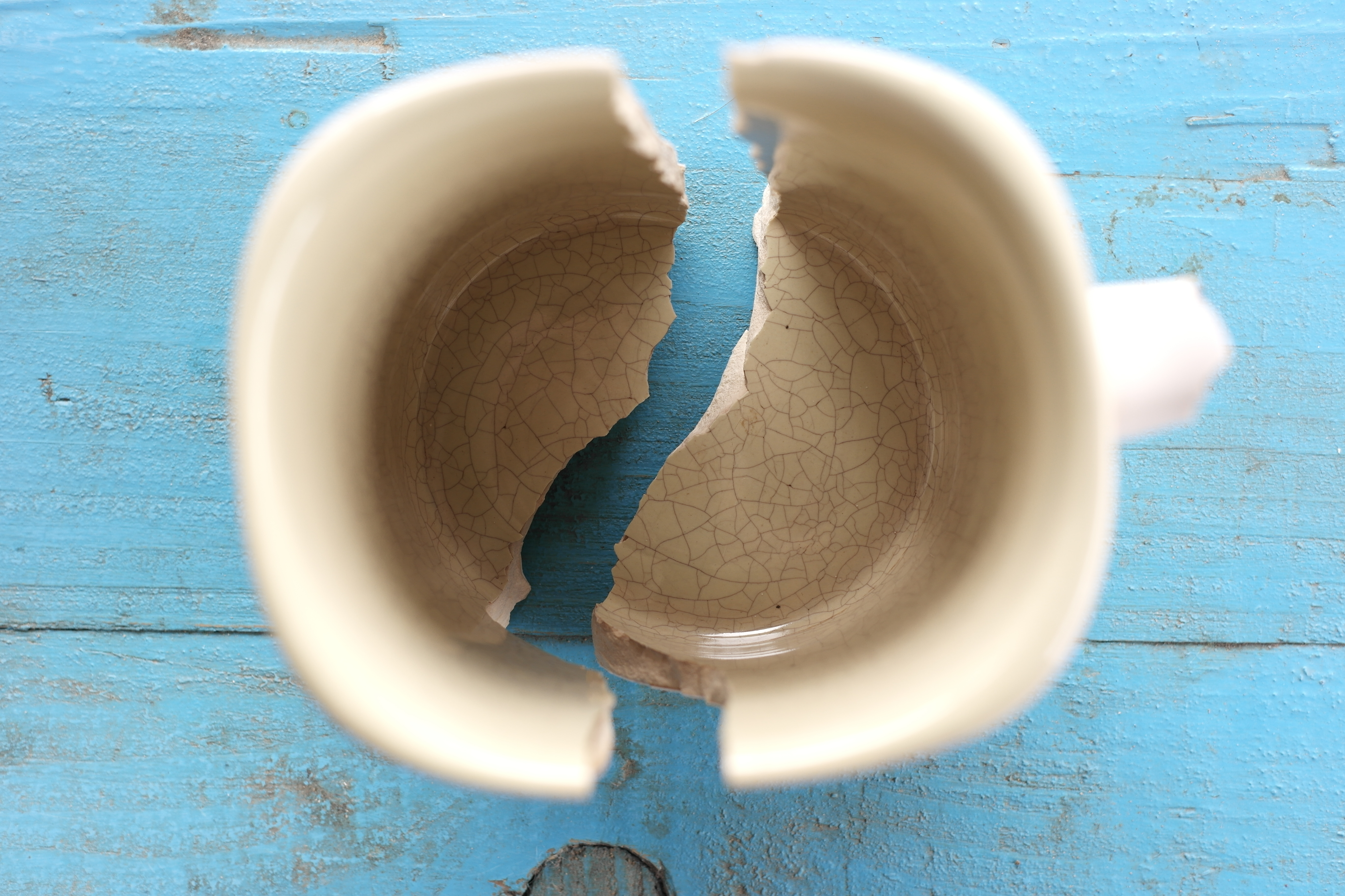
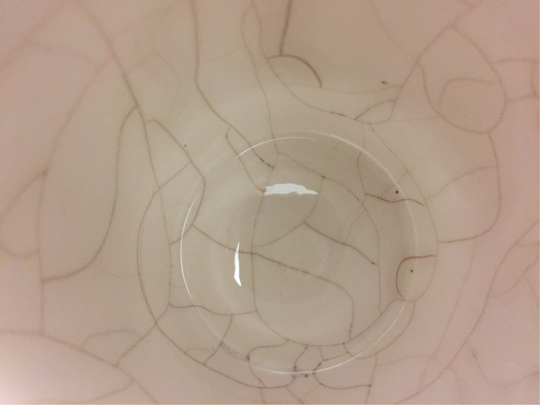
Usually, the surface takes on a crazed appearance like old pottery (Figure 1). The inside of this coffee mug has a crazed appearance due to thermal cycling in an automatic dishwasher. This also happens to molds and dies, ruining their integrity, and leading to failure – unless a material is used that can withstand the thermal environment.

Figure 1. Crazing on Ceramic Surface
Metallurgical phase changes can make heat checking worse if the metal transforms from one solid phase to another upon heating, or vice versa on cooling. This is particularly true when two phases have different crystalline structures or densities.
If heat checking is a potential issue in your application, you should consider using a material with a high thermal fatigue resistance parameter (Q). It is calculated as: ![]() and has the units of W/m or BTU/ft hr. A high thermal conductivity (κ) minimizes the thermal gradient within the material, decreasing the differential thermal expansion. A high yield strength
and has the units of W/m or BTU/ft hr. A high thermal conductivity (κ) minimizes the thermal gradient within the material, decreasing the differential thermal expansion. A high yield strength ![]() minimizes the amount of plastic deformation that occurs on heating and cooling, reducing the tendency to initiate a crack. A high elastic modulus (E) increases the stress at a given amount of thermal strain, so the lower the modulus, the better. A high thermal expansion coefficient (κ) also increases the thermal strain.
minimizes the amount of plastic deformation that occurs on heating and cooling, reducing the tendency to initiate a crack. A high elastic modulus (E) increases the stress at a given amount of thermal strain, so the lower the modulus, the better. A high thermal expansion coefficient (κ) also increases the thermal strain.
The (1 – ν) term accounts for a biaxial stress state. This assumes that an entire surface is heated, so the material expands in two directions instead of one. Most metals have a Poisson’s ratio (ν) of around 0.3, so when comparing different materials, this term can usually be safely ignored. Note also that the equation for Q has the term ![]() in it, which is the elastic resilience of the material. Therefore, thermal fatigue is yet another failure mode that you can protect against by using a highly resilient material.
in it, which is the elastic resilience of the material. Therefore, thermal fatigue is yet another failure mode that you can protect against by using a highly resilient material.
Alternatively, when you know what the thermal cycle will be, you can use the fatigue strength at the mean temperature in place of the yield strength for the thermal fatigue resistance parameter. This would require you to also have the appropriate elevated temperature fatigue data for the material of interest. However, when you are simply making a first pass through multiple materials for a thermally cycled application (such as a water-cooled plunger for die casting of aluminum alloys), the yield strength provides a perfectly reasonable comparison.
Thermal shock is similar to thermal fatigue, except that the failure occurs during a single, rapidly applied thermal load. While thermal fatigue is a cumulative process over many cycles, thermal shock failures are immediate. This is usually more of a concern in ceramics or other brittle materials that lack ductility, where the initiation of a crack would likely lead to catastrophic failure. Thermal shock failures are familiar to anyone who has ever accidentally set a piece of cold ceramic dinnerware onto a hot stovetop and watched it break.
The thermal shock resistance parameter (RT) has the same units as the thermal fatigue resistance (W/m or BTU/ft hr), and the formula is virtually identical, with tensile strength replacing yield strength: ![]() . Since tensile strength is higher than the yield strength, if a material has a high thermal fatigue resistance parameter, it will also have a high thermal shock resistance parameter. RT describes how well a material can theoretically resist cracking (initiating a new crack), which is why the tensile strength is used in the formula instead of the yield strength.
. Since tensile strength is higher than the yield strength, if a material has a high thermal fatigue resistance parameter, it will also have a high thermal shock resistance parameter. RT describes how well a material can theoretically resist cracking (initiating a new crack), which is why the tensile strength is used in the formula instead of the yield strength.
In defining thermal shock resistance, some engineers prefer to replace the tensile strength with the plane strain fracture toughness K1C, as follows: ![]() . In this case, the units become
. In this case, the units become ![]() or
or ![]() . The second equation would be appropriate if there are pre-existing cracks in the material, so the formula then describes theoretical resistance to catastrophic propagation of an existing crack. If you have ever had a small crack in your windshield quickly grow larger due to swings in the outdoor air temperature, then you are familiar with this particular failure mode.
. The second equation would be appropriate if there are pre-existing cracks in the material, so the formula then describes theoretical resistance to catastrophic propagation of an existing crack. If you have ever had a small crack in your windshield quickly grow larger due to swings in the outdoor air temperature, then you are familiar with this particular failure mode.
Selecting materials with high thermal fatigue and shock resistance is crucial for extending component lifespan in thermally demanding applications. By prioritizing properties like thermal conductivity, yield strength, and tensile strength, engineers can reduce the risks of thermal cracking and deformation.
Learn more about material strain testing, see our related blogs: